Tapping a Link with G-TAP A Series 2
To tap a link with G-TAP A-TX21 follow the below steps :
|
1.
|
Disconnect any existing link between two network devices , example; a connection between an access switch and a distribution network. |
|
2.
|
Reconnect the link so that data flows through the tap. |
|
3.
|
Connect the test traffic to Network A / B ports, close with tap relay in passive mode, and verify that traffic flows through the G-TAP . |
|
4.
|
Once the traffic flow is confirmed in passive mode, switch it back to active mode and connect the production link. |
Note: The above step is not applicable for G-TAP A-SF21.
|
5.
|
Connect the Ethernet cable from one network device to the Network A port. |
Note: The above step is not applicable for G-TAP A-SF21.
|
6.
|
Connect another cable from the second network device to the Network B port. |
|
7.
|
Connect the Monitor/Tool ports either to a network analysis tool or to a GigaVUE data access switch for intelligent distribution to multiple tools. |
|
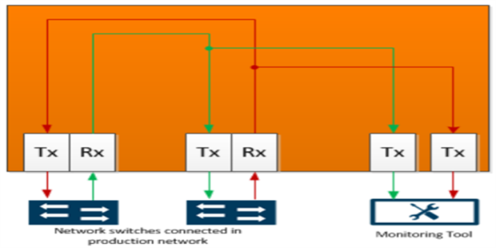
Figure 4
|
G-TAP A-TX21 Data Flow per Group |
Once the tap is operating successfully in active mode, traffic is sent to the Monitor/Tool ports, as shown in G-TAP A-TX21 Data Flow per Group . If the primary sources of power is lost and backup battery drops to 5 percent of charge capacity , then G-TAP A-TX21 will automatically close its relays and switch back to passive mode .


